

OTDR
optical time-domain reflectometry
In optical fiber communications, the losses in optical fibers can be measured with optical time domain reflectometers. The measuring method works similar to radar but works with very low light levels and helps to localize poor fiber splices or faulty optical components.
In Optical Time Domain Reflectometry a fast light pulse is injected into the measured system (for example a fiber optic line). OTDR measurements are similar to TDR measurements, but are based on emitting a series of light pulses, e.g. by means of a laser. Here, the time of the reflections is determined from the reflection loss by measuring from the same end of the fiber how much light passes over the Rayleigh backscatter or is being reflected from individual locations along the fiber. OTDR measurement technology provides a snapshot of the entire connectivity of fiber optic networks, including all link points, splices, and fiber sections.
With help of a fast ADCs or TDCs the time parameters of the reflections and scatterings are measured in order to determine the location of the fault.
Please also read our detailed article on this topic.
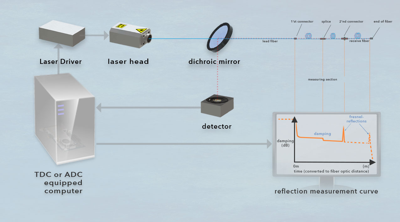
Scheme of an OTDR measurement setup for an optical fiber: A light source (in this case a laser) generates a light pulse with a known pulse length and wavelength, which is coupled into the fiber (blue). The distance to be measured is between a lead fiber and a receive fiber. Light is permanently scattered back by Rayleigh scattering (pink), e.g. fiber splices lead to measurable signal attenuation. Events with Fresnel reflections (e.g. by connectors) reflect larger portions of light. The returning light is directed into a detector and analyzed. The emission of the pulse serves as a start signal for an analog-digital converter. Thus, a measurement can be made of the time it takes for the pulse to reach a reflective event and return to the detector of the measuring device. During this measurement, the pulse passes through the fiber. The pulse is reflected at the end of the fiber at the latest, which means that fiber breaks can also be localized. As a rule, additional reflections or attenuations of the signal already occur on the way to the end of the fiber, e.g. at splices or connectors, indicating their distance from the pulse source. (© cronologic GMBH & Co. KG)