

Time Domain Reflectometry
TDR (Time Domain Reflectometry) is an electronic measurement method, common since the early 1960s, that measures reflections along a conductor. It belongs to the category of Distance-to-Fault (DTF) measurements. TDR measurements provide meaningful information about the broadband behavior of transmission systems. This involves determining the impedance characteristics of cables, measuring their lengths, and locating the position of splices and connectors and the associated losses. The pendant to TDR measurements from the field of optics consists of OTDR measurement techniques, which we discuss in a separate article.
How TDR analysis works
A TDR unit works much like a radar, which is why simple devices for such measurements are often referred to as cable radars. To test a conductor, the TDR sends a characteristic pulse onto the conductor and registers its reflections, which occur due to discontinuities along the conductor. Provided the conductor has uniform impedance and is properly terminated, no (or minimal) reflections will occur, and the remaining energy of the pulse will be completely absorbed by the termination at the distant end. If, however, there are impedance fluctuations, part of the incident signal will be reflected back to the source, as shown here.
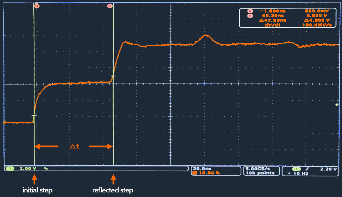
To implement this measurement method, a fast step signal, and a broadband oscilloscope, for example, can be used to measure reflections (or transmissions). Therefore, the term TDR has also become established as the usual designation for an oscilloscope with this capability. The incoming voltage step and the reflected voltage waves are algebraically accumulated and monitored by the oscilloscope. In this measurement method, the amplitude of the signal registered by the detector and monitored by the oscilloscope is a function of the system impedance, i.e. it is also a step signal interspersed with the corresponding impedance jumps. Due to the broadband receiver architecture, such measurements result in a comparatively poor signal-to-noise ratio.
The TDR measurement is based on the ratio of reflected to transmitted voltage, the reflection coefficient. Reflections generally have the same shape as the incident signal, with their sign and magnitude depending on the change in impedance level. If the impedance is increased by a step, the reflection has the same sign as the incident signal; if the impedance is decreased by a step, the reflection has the opposite sign. The magnitude of the reflection depends not only on the change in impedance but also on the losses in the conductor.
The characteristic of the discontinuity, e.g. resistive, capacitive or inductive components of the impedance response, results from its reaction. A bump indicates a high-impedance event (e.g., an open circuit, a reduction in conductor width, an inductive discontinuity). A dip indicates a low impedance event (e.g., short circuit, increase in line width, capacitive discontinuity). The impedance of simple discontinuities can be calculated by measuring the ratio between the input voltage and the reflected voltage. As mentioned earlier, the position of the discontinuity can also be calculated as a function of time. This is done by determining the propagation speed along the transmission line.
Time domain reflectometry is a very powerful tool for analyzing the appearance of various structures as a function of time or distance. TDR measurements nevertheless have systemic limitations, especially when measuring active systems. This is because when analyzing closely spaced discontinuities, the observable resolution depends on the pulse width used for the excitation pulse. If this pulse width is too large, the reflections are so close together that they can no longer be resolved and appear as a single reflection. High-resolution measurements are consequently based on narrow pulses with correspondingly high resolution in data acquisition. However, when the pulse width is reduced, the spectrum of the signal occupied in the frequency domain increases. To achieve better resolution in the time domain for measuring smaller discontinuities, larger bandwidth is used for the measurement. Larger measurement bandwidths, on the other hand, have a greater probability of interfering with active systems.
Another issue is the pulse repetition rate. The structure of the measured assembly can lead to the registration of some reflections at fast successive pulses, which have their actual origin in the following pulse. The pulse repetition rate determines the maximum unambiguous range of the measurement (the alias-free measurement range), and is, therefore, a measure of how deep into the structure of the assembly the measurement can be made.
Due to these limitations, known TDR measurement methods have been and are being modified and extended over the years. For example, different pulse characteristics are used in the various devices for TDR measurements. In many cases, single pulses are transmitted along the conductor by the scanning module, and a half-cycle sinusoidal waveform is commonly chosen as the pulse shape. The resolution of all these devices depends on the width of the pulse. Narrow pulses can provide good resolution, but they have high-frequency signal components that are attenuated in long cables. With longer cables, larger pulse widths are used, which reduces the measurement resolution.
Some TDR instruments provide the ability to measure the impulse response of the system under test in the frequency domain and then mathematically calculate the inverse Fourier transform of the data to determine the time domain response. This approach works because the Fourier Transform of the network reflection coefficient as a function of frequency is the reflection coefficient as a function of time - that is, in the case of a TDR measurement, the distance along a transmission line. These devices thus operate similarly to frequency domain reflectometers (FDRs) or network analyzers (VNAs). FDR measurements are built over time by measuring the reflected steady-state amplitude and phase over numerous discrete frequencies. In contrast, TDR measurements are built by measuring the reflected voltage at discrete time points. The main difference between the traditional TDR and VNA time-domain techniques is that the analyzer makes swept-frequency response measurements and then mathematically converts the data into a TDR-like display. Comparing the two methods, TDRs have better distance-to-fault accuracy than FDRs because they measure the reflection coefficient as a function of time, thus providing a direct reference to the measured distance. When fast and accurate localization of cable and connector faults in the field is required, TDR is usually a better choice than FDR. If, on the other hand, the best possible performance in the frequency domain is required, FDR-based measurements may be the better choice.
Similar and advanced measurement methods
We would also like to discuss the following TDR-based measurement methods:
- Time domain transmissometry (TDT) should be mentioned as a TDR-related measurement technique. In contrast to TDR, the transmission and not the reflection of a pulse is measured here.
- Another form of TDR measurement is the Spread-Spectrum Time Domain Reflectometry ( SSTDR), which allows the detection of temporary faults in live wires. This measurement technique is used to identify defects, usually in electrical wires, by observing reflected spread-spectrum signals. This type of time domain reflectometry can be used in various high-noise and live environments.
- The optical time domain reflectometer (OTDR) is certainly one of the most advanced types of TDR. It is an equivalent measurement technique in which transmission characteristics of optical fibers are analyzed.
- Multicarrier Time Domain Reflectometry (MCTDR) has already proven to be an efficient method for online diagnosis, as it allows precise control of the measurement bandwidths and thus avoids interference with the measured system.
- OMTDR (Orthogonal Multi-Tone TDR) is considered one of the most advanced reflectometry methods. It applies the principles of Orthogonal Frequency Division Multiplexing (OFDM) to the diagnosis of wired networks.
- In Noise Domain Reflectometry (NDR), the reflectometer uses significant noise or broadband signals already present on the line, rather than feeding a signal into the line to locate intermittent faults on live lines. It is therefore a passive test method that allows estimation of the distance to a fault and allows online measurements.
TDR measurements are quick and intuitive to set up and easy to use, so they show their advantages when systems are to be tested in a targeted manner and with as little effort as possible. Therefore, the method is used in many application areas.
Application areas of TDR-based measurements
TDR measurement methods are basically interesting for all areas based on locating faults in electrical conductors or determining the distance to the fault.
- Testing very long cable runs
TDRs have become indispensable for the preventive maintenance of telecommunications lines and the associated provision of signal integrity. Here, for example, corrosion on joints and connectors and leaks in the insulation can be detected. It is possible to localize faults to within a few centimeters.
- Quality assurance in printed circuit board and semiconductor manufacturing.
By observing reflections, exact positions of interruptions or short circuits in assemblies on modern high-frequency printed circuit boards, e.g. due to unsoldered pins of a ball grid array component or short-circuited pins, can be detected. In the semiconductor industry, faulty sections in integrated circuits or chip packages can also be localized non-destructively by means of time-domain reflectometry.
- Process monitoring
Especially in the process industry, TDRs are used for level measurement. Here, the signal is fed in via a probe and reflected at the surface of the medium. The measured reflection time helps to determine the liquid level. The sensors can output the analyzed level as a continuous analog signal or as a switching output signal. The measurement of high-temperature, boiling, or foamy media requires complex error corrections.
- Construction Measurement & Geotechnical Engineering
In many architectural structures, such as dike construction, dams, railroad beds, open pit mining, and bridge construction, time domain reflectometry provides useful information for stability monitoring. As a significantly more accurate alternative to direct resistance measurement with strain gauges, SSTDR measurements in anchor cables, impedance measurements on coaxial cables, or >>> Wiki: ODTR measurements with fiber optic sensors are used for precisely spatially resolved strain and vibration measurements. The aim is to detect any cracks in the concrete or other structural weaknesses using non-destructive methods.
- In the agricultural industry, TDR measurements are used to determine the moisture content in soils and porous media. The wave propagation is primarily measured to determine the permittivity (dielectric constant) of materials in order to draw conclusions about the water content of materials.
- In geotechnical engineering, soil moisture content determination is also useful to determine the rate of water infiltration.
- Localization of interception devices
In surveillance technology, TDRs enables the detection of deviations or splices in telephone lines that are due to Third Party Interference (TPI) activities.
- In the maintenance diagnostics of the aerospace industry, cable diagnostics has become essential to ensure safety and especially electromagnetic compatibility (EMC). The increasing number of embedded electronic systems has led to an escalation in the total length of interconnecting cables. For example, a single Airbus 380 contains approximately 530 km of cables. In this area, the complex wired networks are highly exposed to internal and external conditions such as moisture, corrosion, localized heating, aging, and mechanical damage. Defects here can easily lead to deterioration of cable shielding and, as a result, drastically exacerbate the emissivity and vulnerability of electrical equipment. However, online diagnosis of such complex wired networks is challenging.
To enable live monitoring of these wired networks, new variants of TDR measurements are constantly being developed. A key issue here is to perform measurements that protect the target system from unwanted interference during normal operation and yet detect soft errors that generate only weak echoes and are thus difficult to detect. In short, the test signals must not interfere with the useful signals. At this point, we will only mention some of these measurement techniques for such embedded diagnostics, without going particularly deep into how they work: Quite common is Spread Spectrum Time Domain Reflectometry, in which the spectrum of the emitted signal can be shifted to avoid interference with individual elements of the onboard network. Also used here are methods of Frequency Domain Reflectometry (FDR), Phase Detection FDR (PDFDR), and Mixed-Signal Reflectometry (MSR), which are based on the measurement of the complex response of a network for individual frequencies in the desired bandwidth. Further measurement methods of embedded EWIS diagnostics, which are intended to make the location of errors more reliable, are based on the use of multicarrier signals, such as those known from OFDM (Orthogonal Frequency Division Multiplexing). To improve the signal-to-noise ratio, many slowly modulated narrow-band signals are used instead of one fast modulated wide-band signal and are modulated independently of each other, thus increasing the spectral efficiency. Multi-carrier time-domain reflectometry (MCTDR) should be mentioned in particular.
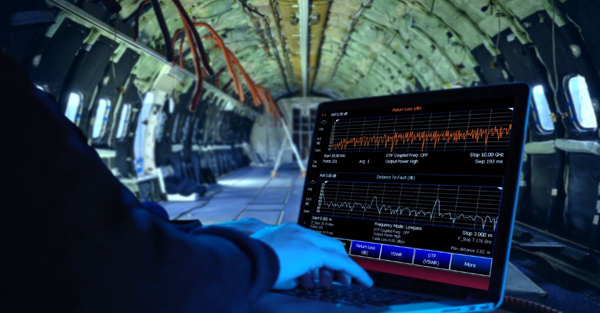
Image Sources:
reflection of a wave component, creator: Oleg Alexandrov, Image rights: public domain, picture has been color matched and taken from: https://commons.wikimedia.org/w/index.php?curid=3148138
measurement with a laptop computer, Adobe CC / Framestock (No. 159478397, composing)
Author: Uwe Thomaschky
Remark:
This article about TDR applications for our products is intended to give visitors to our website who are interested in such topics a little insight. We ourselves are primarily concerned with the data acquisition requirements of our customers and are not active in the telecommunications industry, the process industry or semiconductor manufacturing, nor do we build surveillance technology or equipment for aircraft maintenance. The following content is therefore not to be understood as a scientific treatise, but also reflects subjective impressions.