

OTDR
An optical time domain reflectometer is the optical equivalent of an electronic time domain reflectometer and is used for the non-destructive testing of optical fibers and systems. OTDR measurements are based on the transmission of a series of light pulses, usually by means of a laser. The time of the reflections is determined on the basis of the reflection attenuation by measuring from one end of the fiber how much light is scattered back via Rayleigh scattering or reflected back from individual points along the fiber.
Today, optical fibers are among the most important elements of modern telecommunications networks. Long-distance, high-bandwidth interconnections and the implementation of the Open Systems Interconnection (OSI) model would not be possible without these transmission media. When characterizing fiber optic networks, OTDR measurement technology provides a snapshot of the entire connectivity, including all link points, splices, and fiber sections. It serves as a reference for subsequent commissioning and is used for quality assurance including the timely assessment and elimination of mechanical damage, which is considered the main cause of fiber optic transmission degradation.
OTDR measurements are similar to TDR measurements, but are based on emitting a series of light pulses, e.g. by means of a laser. Here, the time of the reflections is determined from the reflection loss by measuring from the same end of the fiber how much light returns via the Rayleigh backscatter or is being reflected from individual locations along the fiber.
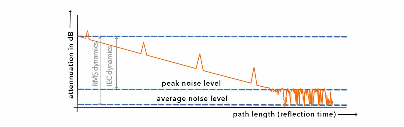
The characteristics of these earlier reflections are very different from those of the fiber end. In Rayleigh backscattering, the amount of backscattered light is very small. In contrast, a Fresnel reflection loss is much larger since considerably more light is reflected back here and thus usually leads to a clear peak in the measurement curve.
The data acquired on the scattered or reflected light (backscatter) is used to characterize the optical fiber or to localize faults. The intensity of the returning pulses is measured, integrated as a function of time, and finally visualized as a function of the fiber length. The losses resulting from reflections and scattering accumulate with the material-related losses of the fibers to form the total attenuation of the transmission link.
The measurement technique of optical time-domain reflectometry is becoming increasingly important in information and data transmission technology, especially since the different types of attenuation can be evaluated on the basis of the measurement results and the measured transmission links can thus be optimized in a targeted manner.
Therefore, OTDR measurement methods are indispensable in fiber optics today and are widely used in telecommunications in particular, with the following information being of particular interest:
- the fiber attenuation (ORL, Optical Return Loss) of individual link sections.
- the distance to points with high loss or, respectively, high reflectivity, to check the quality of the components used or to any defective points such as misalignments due to too tight bending, crushing, impurities in connectors, defective splices, etc.
- the distance to the fiber end, e.g. to detect damage such as fiber breaks or defective connectors
Background information:
The conduction of light in an optical fiber occurs by total internal reflection at a boundary layer between a material with a high refractive index and a material with a low refractive index. Changes in the refractive index along the guide lead to reflections or scattering effects, which form the basis for OTDR measurements. An important parameter of optical fibers is the optical attenuation, i.e. the light loss during the transmission of light. It is calculated from the ratio of the power of light at the beginning of the fiber to the power of light at the end of the fiber and is expressed in decibels (dB).
The cause of loss of light in optical fibers (scattering and absorption) is determined to a large extent by the material (i.e., glass quality in terms of homogeneity) and the structure of the optical fiber. Thereby, scattering losses are mainly caused by Rayleigh scattering, which has its origin in the discontinuities of the refractive index along the optical fiber.
The (strongly wavelength-dependent) absorption results, for example, from undesirable admixtures of various substances to the fiber medium. In addition to the attenuation of light by the material, there are additional attenuation effects caused by coupling and splice points. This type of attenuation is called Fresnel reflection. When evaluating OTDR measurements, it is, therefore, crucial to know the possible causes of attenuation.
In order to optimize optical transmission lines as well as to localize and eliminate faults, it is important to correctly analyze the magnitude of the attenuation values from the optical fiber's junctions or connectors and to consider them in a realistic relation to the material-induced attenuation, which is mainly caused by Rayleigh scattering.
Now, we would like to introduce the basic structure of an OTDR device:
OTDR Method of Operation
OTDR measurements are based on two optical effects: Fresnel reflection and Rayleigh scattering. Both are detected in an OTDR measurement. Here is a simplified scheme of such a measurement:
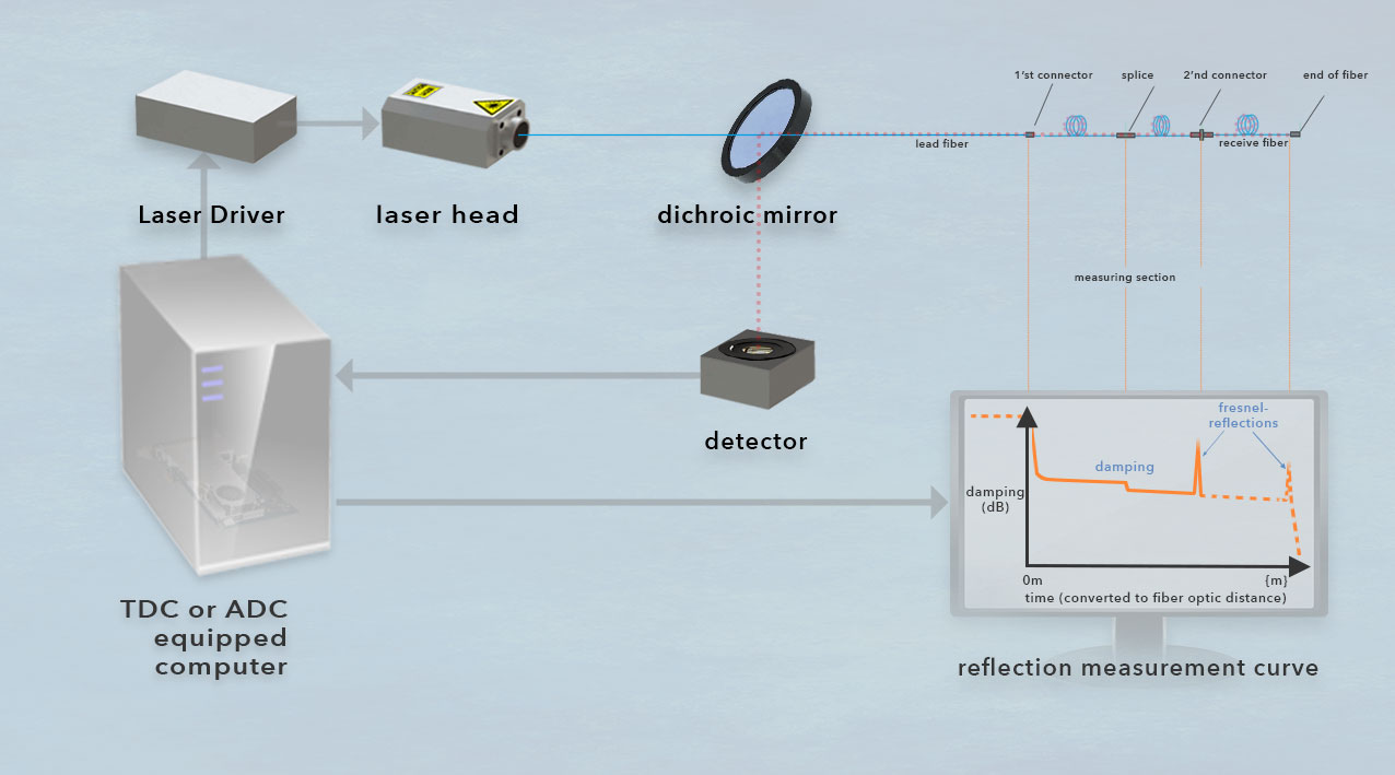


As already mentioned, short pulses provide better resolution, but their range is limited because the pulse power may not be sufficient to reach the end of the fiber at all. If this effect is counteracted with long pulses, the dynamic range increases, but the resolution of the measurement deteriorates. In order to measure larger distances despite the limitation of the resolution by the duration of the measuring pulse, the measuring time can be increased. This makes averaging (and thus a smoothing of the measuring curve) possible. The results then become more accurate with a longer measurement duration. Modern OTDR devices make thousands of measurements over a measurement time of several seconds and average the received measurement values.
The parameters wavelength, pulse width, measuring range, dynamics, and curve averaging/measuring time consequently have to be carefully adapted to the conditions and the measuring section for each measurement. The tested fiber optic measurement sections are often supplemented by a lead fiber and a receive fiber of the same fiber type. The former is used to make the distance to the first connector to be measured large enough so that this can be detected outside the dead zones. The receive fiber is used to capture the last connector outside the dead zones. When measuring with longer pulse widths, e.g. to measure long fiber distances, more energy is introduced into the measurement. As a result, the dead zones also become longer, and consequently longer lead- and receive-fiber lengths are required.
To increase accuracy, fiber optic links are measured bi-directionally in a so-called loop, if physically possible. In this case, the measurement direction is changed so that the lead fiber becomes a receive fiber and vice versa.
OTDR device classes
The ideal OTDR device would be capable of representing very short pulse durations using the smallest possible sampling intervals with very high resolution over a wide measurement range. The latter describes the maximum attenuation that may occur between the measuring device and the event to be measured, on the condition that the measurement can still determine the event within acceptable accuracy limits. With regard to the measurement range, however, there is a system-related limitation with OTDR: short laser pulses often have a large bandwidth, which is further broadened by the dispersion of the optical fiber. This leads to an unavoidable degradation of spatial resolution, especially for long-haul fiber links.
This limitation of the common OTDR measurement method is countered e.g. in TCSPC-based OTDRs with the use of high-resolution ADCs, which are in some cases replaced by TDCs to use time channels with a width of a few picoseconds. The goal here is to shorten measurement times for monitoring increasingly larger fiber optic networks, if possible, and to replace personnel-intensive on-site measurements with long-distance measurements. The combination of the high sensitivity of single-photon detectors (SPD) with the high temporal resolution of TDCs provides a higher dynamic range and a better spatial resolution for such applications.
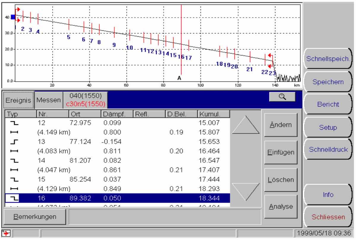
For measuring comparatively short distances, portable fiber optic fault locators have been available for OTDR for some years now, which show the return loss in relation to the fiber length on their display. Today, the measurements are so precise that, in addition to the graphical representation of said measurement curve, very user-friendly visualized representations of the fiber line are also displayed. The interpretation of the data can be carried out with such measuring devices even by non-experts.
Even though the interpretation of OTDR measurement data is much easier today, the requirements for data acquisition have increased over time, e.g. due to the increasing use of multiplexing methods in data transmission. For example, single-photon counting has also found its way into this measurement technology (Photon Counting OTDR, PC-OTDR).
Often, the price and ease of use are the primary considerations for these optoelectronic tape measures, which primarily measure the distance to fault, as the devices are designed to collect field data and perform rudimentary data analysis. In conjunction with PC-based software, a somewhat broader data collection and data analysis may be possible with certain vendors.
Significantly more complex are "remote fiber testing systems" (RFTS), which allow automated testing of entire fiber networks from a central location. In these OTDR-based measurements, a central computer controls the operation of multiple test components at key points in the fiber network. From these points, the fiber network is tested and when unusual discontinuities in the network are detected, their location is noted. In many cases, this is done by referring to a history of the acquired data, which is recorded in a system-specific database. Network managers are thus able to monitor the fiber optic infrastructure very reliably.
By the way: Especially in quantum research, several measurement methods are based on the basic principle of OTDR.

Author: Uwe Thomaschky
Remark:
This article about OTDR applications for our products is intended to give visitors to our website who are interested in such topics a little insight. We ourselves are primarily concerned with the data acquisition requirements of our customers and are not active in the telecommunications industry or in fiber optic technology. The following content is therefore not to be understood as a scientific treatise, but also reflects subjective impressions.