


Constant Fraction Discriminator
CFD, Time-to-Digital Converter, , TDC, Time Tagger, Time-Walk, Leading Edge Discriminator, Time-over-Threshold (ToT), Digitizer, TCSPC, ToF-MS
A constant fraction discriminator (CFD) is an electronic circuit designed to extract precise timing information from detector pulses (e.g., from MCPs, PMTs, SiPMs, or APDs) that have fluctuating pulse amplitudes but a consistent rise time.
Standard threshold discriminators (Leading Edge Discriminators, LED) suffer from an amplitude-dependent timing error known as time-walk: high-amplitude pulses cross a fixed threshold earlier than smaller pulses, degrading the overall timing resolution.
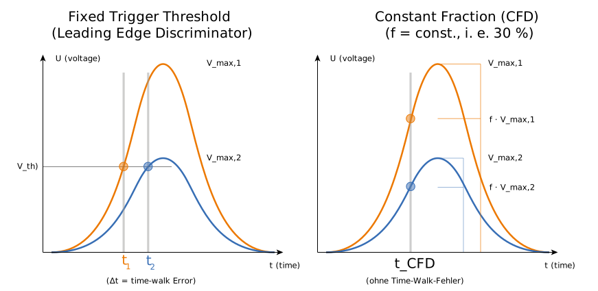
Comparison: A fixed threshold (left) causes an amplitude-dependent time-walk error (Δt). A CFD (right) triggers at a constant fraction of the peak height, producing identical timestamps regardless of pulse amplitude. Image source: CC BY-SA 2.5 <https://creativecommons.org/licenses/by-sa/2.5>, via Wikimedia Commons
A CFD eliminates time-walk by triggering not at a fixed voltage, but at a constant fraction (f, typically 20–40%) of the pulse height:
- The input pulse is split into two paths.
- Path A is inverted and attenuated by a fraction f.
- Path B is delayed by a precise duration t_d.
- Summing both paths yields a bipolar waveform whose zero-crossing point provides an amplitude-independent, picosecond-accurate timestamp.
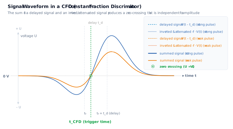
Operating principle of a CFD: Summing a delayed pulse with an attenuated, inverted pulse creates a zero-crossing point that remains temporally fixed for all pulse amplitudes.
A Constant Fraction Discriminator (CFD) only achieves peak picosecond-level performance when its parameters—specifically the delay time (t_d) and the attenuation factor (f, the fraction)—are precisely tailored to the specific pulse characteristics of the detector in use (e.g., MCP, PMT, SiPM, or solid-state detectors).
To minimize timing jitter and maximize temporal resolution, the trigger event (the zero-crossing of the summed signal) must occur at the steepest portion of the pulse’s leading edge — the point of maximum slew rate, typically located at the inflection point between 20% and 40% of the total pulse amplitude).
CFD and Modern Methods of High-End DAQ
In modern measurement setups (e.g., ToF mass spectrometry, TCSPC, LIDAR, or nuclear physics), high-resolution digital methods are increasingly replacing traditional analog CFD hardware:
- Time-over-Threshold (ToT) with High-Resolution TDCs: If TDCs (such as the xTDC4) capture both the rising and falling edges, the pulse width (ToT) can be used to mathematically correct the amplitude and thus the time-walk, provided the pulse shape is known and reproducible. Please note: Since the falling edge of detector pulses is usually flatter, determining the pulse width is more susceptible to amplitude noise at the trigger threshold than merely sampling steep edges.
- Multi-Threshold Measurement via Channel Splitting: If the signal is split across several TDC channels with staggered threshold values, only the steep rising edge is sampled at multiple points. The time walk can then be calculated based on the steepness of the slope. Using multiple measurement points improves the noise performance.
- Digital Waveform Processing with High-Speed Digitizers: With multi-gigasample digitizers (cronologic Ndigo series), the complete waveform is digitized. Algorithms such as digital CFD filters (dCFD) or mathematical curve fitting run directly on the FPGA or in post-processing, providing maximum noise suppression while remaining independent of asymmetrical or varying pulse shapes.